Turbine Blade Inspection Borescope: Probe Diameter & Articulation Guide
About the manufacturer
Shenzhen Jeet Technology Co., Ltd. is an industrial videoscope manufacturer based in Shenzhen, China. The company is a national high-tech enterprise and Shenzhen specialized-and-innovative SME, certified to ISO 9001/14001 and GJB9001, with products carrying CE and RoHS marking. Its aviation line covers the JX Series motor-driven 3D measurement videoscope, the K Series motor-driven HD videoscope, the F Series split-design 3D measurement videoscope, and the T51X Series handheld videoscope. The technical specifications cited in this article apply to those models.
A high-pressure turbine blade can fail without ever showing a symptom on the outside. A crack initiates at a cooling-air hole, propagates across the platform, and by the time it is visible from the fan-blade side, the part is already beyond serviceable limits. That is the reason borescope inspection sits inside regulated maintenance programs rather than beside them — under an FAA airworthiness directive such as the 2026 LEAP-1A AD for certain HPT stage 1 blades, inspection intervals, results, and disposition are documented requirements, not informal judgment calls.
Yet the instrument decision is surprisingly often made on the wrong variable. Buyers ask for the highest pixel count on the datasheet. Then the probe arrives and three things get discovered on the first job: it does not clear the blade gap, it cannot hold position at the tip, and the image goes flat two metres in.
This guide works backwards from the inspection itself. Probe diameter is a hard physical gate. Articulation angle determines coverage of the zone behind that gate. Working length determines whether the signal survives the trip. Illumination determines whether the crack is visible once you are there. These four are not independent, and choosing them out of order is the most common reason a borescope purchase disappoints.
Why turbine blade inspection is a different category of borescope work
A casting inspection and a turbine blade inspection share the same instrument category and almost nothing else. In a foundry, the question is usually binary: is the cavity clean, or does it still contain core sand, and is the surface porous. The access port is generous, the path is short, and moderate image quality resolves the decision.
Hot-section blade inspection reverses every one of those conditions.
The access path is defined by geometry you did not choose. Airfoil platform gaps, seal-land bores, and root interfaces are fixed by the engine design. The inspection has to be performed through an existing port, which means the probe diameter is dictated by the engine, not chosen by the inspector. A 2.2 mm probe that navigates a blade gap cannot be pushed into a 6 mm seal bore without losing the very access that makes it useful.
The consequence is that the smallest available probe is not automatically the right one. Below roughly 1.8 mm, light collection becomes the binding constraint: the same resolution sensor receives fewer photons through a smaller aperture, so images darken fast and fine surface texture — which is precisely what distinguishes a manufacturing scratch from a propagating crack — tends to disappear. Aviation inspection therefore operates in a narrow band where the probe is as large as the gap permits and no larger.
Path complexity is the second difference. A blade tip inspection is a straight-in view along the span. A root or platform inspection requires navigating around an adjacent blade, turning the tip to look back at a surface oriented away from the insertion axis, and holding that position while the operator focuses and records. That is a three-way articulation problem, and it is where probe diameter and articulation angle stop being separate specifications and start being one coupled decision.
Probe diameter: the gate that cannot be negotiated
Probe diameter is the only specification in the entire purchase that cannot be solved with better technology downstream. If it does not fit, nothing else matters. Every other parameter is a trade-off; this one is a gate.
The discipline that prevents expensive mistakes is simple and routinely skipped: measure the actual access port before selecting the instrument, and specify the probe at least 0.5 mm below that measured figure to leave clearance for articulation swing. The JEET JX Series is specified from 1.0 mm through 8.0 mm to cover this range in one platform, with 1.0 mm and 1.8 mm for blade gap and cooling passage work, and 4 mm, 6 mm and 8 mm where the port is generous.
The practical mapping to blade inspection zones
| Probe diameter | Typical turbine access target | Trade-off you accept |
|---|---|---|
| 1.0 mm | Blade-tip cooling holes, seal-land gaps, narrow oil passages | Lowest light level; shortest working length is strongly preferred |
| 1.8 – 2.2 mm | Blade gaps between adjacent airfoils, platform edges | Requires good illumination discipline; optics not interchangeable with larger platforms |
| 2.8 – 4.0 mm | Blade roots, stages with removable spacers, combustor ports | Balanced configuration for general hot-section work |
| 6.0 – 8.0 mm | Casing interiors, large bores, combustor liner and nozzle guide vane areas | Will not clear a blade gap; use only where the port allows it |
A caution that applies to any diameter quoted in any datasheet. Verify whether the stated figure is the bare tube or the working outer diameter including strain relief and any coating. On short probes the difference is small; on a long insertion tube it is enough to lose clearance in a tight gap. JEET specifies working outer diameter so that the figure you measure against is the figure you receive.
Articulation angle: coverage is not the same as reach
Once the probe clears the port, articulation decides what you see. This is where datasheet vocabulary gets muddy, because "360° articulation" is used for two different things.
360° all-way articulation
The probe tip can be steered in every direction from the handle — up, down, left and right — from a straight insertion axis. That is the requirement for blade root and platform inspection, where the surface of interest faces away from the insertion path. The JX Series and K Series both use this all-way motor-driven configuration, with joystick control and a one-touch lock to hold position.
Four-way articulation
Up/down plus left/right, which is a smaller mechanical envelope and generally lighter in the cable. It suits routes with bends but not surfaces that sit directly behind the tip.
Bending angle is a separate number
It describes how far the distal section deviates from straight, and it is the figure quoted most loosely. Two practical implications for blade work:
A tip that bends to 190° can turn back on itself, which is what lets you inspect a surface perpendicular to the insertion axis. A probe limited to 90° can only look forward along the path — useful for a blade tip, inadequate for a platform underside.
The other implication is length-dependent. Bending resistance rises with insertion length. A probe specified to 190° over 1.5 m may deliver roughly 100° over 8 m. This is physics, not a manufacturing defect, and it is why a long probe quoted at the same bending angle as a short one is a different instrument. JEET states the reduced figure explicitly for long configurations rather than quoting the short-length headline across the range.
Working length: the specification most often over-ordered
Working length is where instinct is usually wrong. The instinct is to order long, in case the target turns out to be deeper than expected. The correct practice is to order the shortest length that reaches the deepest point of the target zone, plus roughly 20% to account for routing around bends.
Three real effects make over-ordering costly. Long insertion tubes transfer less light to the distal tip, so the image degrades. Cable stiffness rises, and for a 1.0–1.8 mm probe the practical limit on manageable length is reached well before the maximum on the datasheet. And articulation response slows, which is precisely the control an operator needs when positioning on a small feature.
For a typical HPT stage inspection through an existing case port, 1.5 m to 3 m covers the depth. JEET specifies 1.5 m, 2 m and 3 m as standard for the JX Series with other lengths configurable; the K Series tube system is configurable from 1.0 m to 30.0 m for long-reach applications such as pipeline and casing work where distance rather than precision drives the requirement.
Signal integrity deserves separate mention because it is a different constraint. JEET's long-distance transmission technology maintains a usable bending angle at extended lengths — the K Series retains approximately 150° or greater at 10 m, and supports signal transmission to 30 m. On a hot-section job, however, image quality at depth matters more than reach. Long reach is the argument for pipelines; it is not the argument for blades.
Illumination and thermal environment
Turbine inspection has two lighting problems that pull in opposite directions. Compressor and fan stages are deep cavities where light does not reach on its own, so illumination must be strong and even. Hot-section parts are frequently specular — polished or coated surfaces reflect a single bright source straight back, and the resulting glare hides exactly the surface texture you are trying to read.
The response is controllability rather than raw output. Exposure suppression keeps polished surfaces readable; exposure compensation opens up large cavities. Negative or contrast modes assist in separating a subtle indication from the surrounding surface finish. White balance in the 5,000–6,500 K range keeps colour rendition stable across parts and operators, which matters when photos become part of the maintenance record.
The JEET JX Series carries either optical fibre or LED illumination, and the K Series tube system can be matched with white light, infrared or ultraviolet sources plus optional auxiliary lighting, so illumination can be matched to the specific zone rather than fixed at purchase.
Temperature deserves the same explicit treatment. Because the insertion tube is tungsten-braided and sized to survive handling, the practical limit under sustained use is governed by heat soak into the distal section rather than by ambient temperature. JEET implements this as an operator-warning threshold rather than a headline rating: the K Series displays a yellow warning from 70 °C and a red alarm at 80 °C, with automatic camera shutdown above 85 °C. The T51X Series uses a comparable scheme, warning from 65 °C and shutting down above 80 °C.
Worked in a way that reads as more honest than a single spec number, because it tells you what the instrument actually does when you push it: treat any hot-section work as intermittent, keep continuous insertion cycles bounded, and watch the on-screen indicator rather than assuming the tube is safe indefinitely.
When measurement is required — and when it is not
Measurement capability is the most expensive line on a videoscope quote and the most frequently unnecessary. Visual inspection answers whether an indication is present and worth documenting. Measurement answers whether it exceeds a limit. Those are different decisions and conflating them inflates both cost and training burden.
Use visual documentation alone when the procedure asks for a condition check and a recorded image. Use comparison measurement when indications are judged against a reference length rather than an absolute value — the JX Series and K Series both support baseline comparison against a standard reference distance. Use 3D measurement when the maintenance decision turns on length, depth, area or clearance, or when the disposition process requires dimensional evidence that survives review.
For dimensional work, the JEET JX Series specifies a standard precision of 0.1 mm and a minimum precision of 0.01 mm with measurement accuracy of 95% or greater, using stereo measurement. The F Series split-design videoscope serves the same measurement class for customers who need the console and probe physically separated. For structural and construction work rather than aviation, the BX Series reaches measurement accuracy of 98% or greater with point-to-point, point-to-line, polyline, area and depth modes.
Choosing measurement where the procedure does not require it is a common and expensive error in the other direction — it adds cost, adds a calibration burden, and produces numbers nobody acts on.
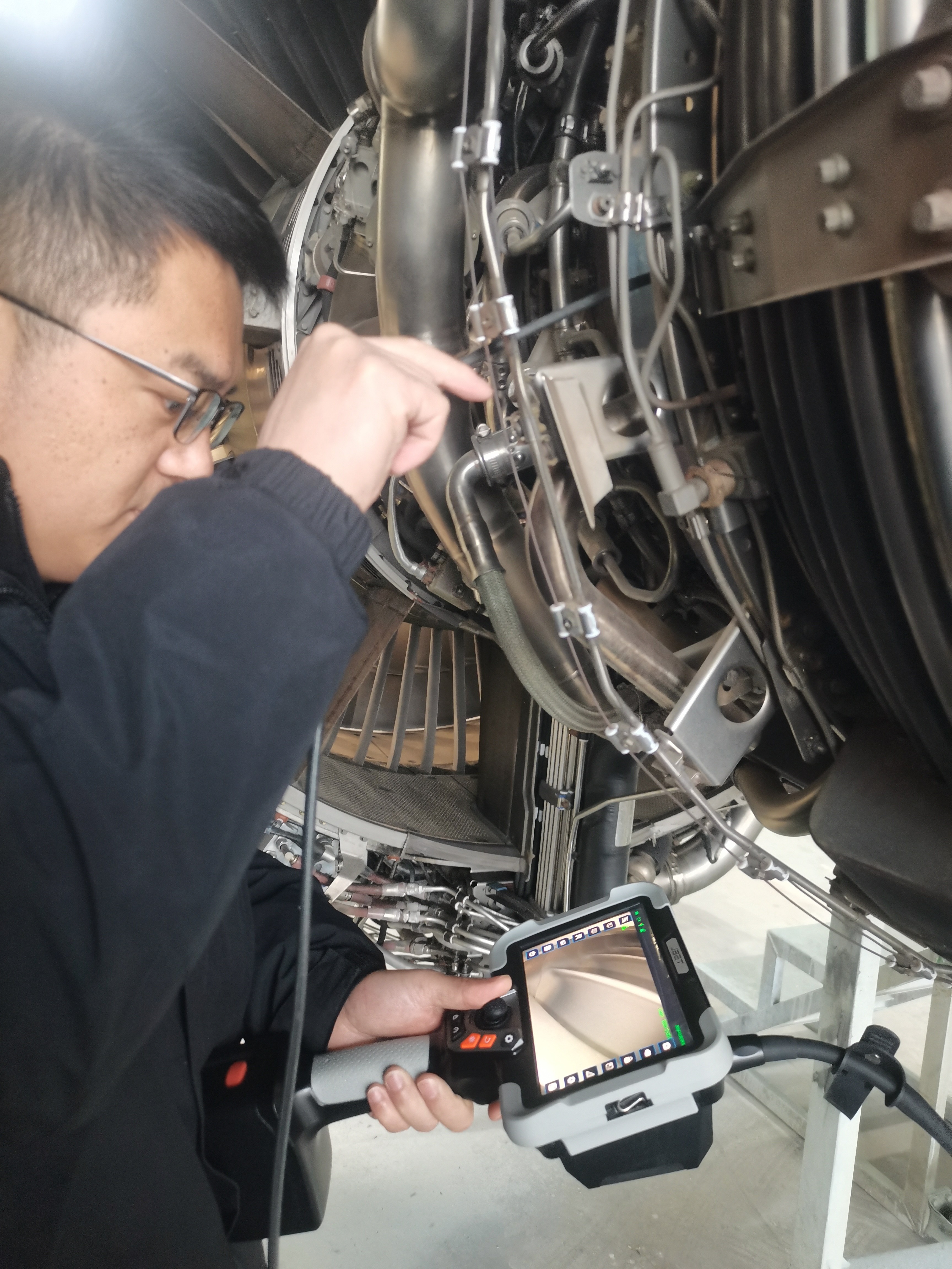
Mapping turbine inspection zones to JEET configurations
The table below maps the four access situations above to specific JEET configurations. These are starting points for evaluation against your engine or asset, not fixed prescriptions — access ports differ by engine type and by inspection port location.
| Inspection zone | Probe diameter | Articulation | Suggested JEET configuration |
|---|---|---|---|
| HPT blade gap, between adjacent airfoils | 2.2 mm | 4-way, motor-driven | T51X Series handheld videoscope — 2.2 mm probe, 4-way articulating, interchangeable tube |
| Blade root and platform interface | 1.8 – 2.8 mm | 360° all-way, motor-driven | K Series motor-driven HD videoscope — all-way articulation with joystick lock, flexible light source options |
| Combustor liner, nozzle guide vanes, internal cavities | 4.0 – 6.0 mm | 360° all-way | JX Series — all-way electric control with 3D measurement if dimensional evidence is required |
| Casing, large bores, stationary hot-section inspection | 6.0 – 8.0 mm | 360° all-way, longer length | K Series with extended tube length — module system accepts lengths to 30 m |
Two supporting notes for crews working to a fixed maintenance schedule
First, modular probe systems reduce the number of instruments a shop must carry. The K Series host, tube system and battery module separate, and one host accepts multiple tube systems across 1.0 mm to 8.0 mm, which means a shop covering blade gaps and casing bores can do it with fewer devices instead of a dedicated unit per task.
Second, thermal protection is not optional on hot-section work. The buffer section between the insertion tube and the handle absorbs the bending moment that would otherwise concentrate at the probe tip, and JEET specifies 42 mm on the T51X tube system and 80 mm on the Pmax for exactly this reason.
w1-05-k-series-modular-system.jpg · K 系列模块化主机、管线系统、电池模块三件套拆解平铺Frequently asked questions
Summary
Turbine blade inspection rewards instruments specified from the access outward, not from the datasheet inward. Measure the real port and subtract clearance, and that sets the probe diameter, which sets the light level you can work with, which constrains the minimum meaningful resolution. Then choose articulation to match the surfaces you must face — all-way motor-driven for anything behind the tip, with the bending angle quoted at your actual working length. Choose the shortest length that reaches the target. Choose measurement only when the disposition process consumes a dimension.
Specified in that order, a videoscope becomes a reliable instrument rather than an expensive one. Specified in datasheet order, it becomes the 2.2 mm probe that will not clear the seal bore, or the 190° articulation that delivers 100° at eight metres.
For background on turbine inspection zones and defect types, see Industrial Endoscopes for Gas Turbine Inspection. For the full parameter framework across all videoscope types, see the Industrial Borescope Guide.
Send us your access constraints
Tell us four things and our applications team will recommend a configuration within one business day:
- Minimum access port diameter (mm)
- Required working length (m)
- Inspection target — for example, HPT blade root, combustor liner, seal-land bore
- Working environment — ambient, hot section, oil-contaminated, or hazardous-area classified
Relevant configurations
- JEET JX Series Aviation Borescope — 360° all-way motor-driven, probes from 1.0 mm to 8.0 mm, stereo 3D measurement from 0.01 mm minimum precision
- JEET K Series Motor-driven HD Videoscope — modular tube system, 1.0 mm to 8.0 mm, lengths to 30 m, selectable white / infrared / UV light sources
- JEET T51X Series 2.2 mm Videoscope — 4-way articulating handheld unit with interchangeable tube system
- JEET F Series 3D Measurement Videoscope — split design with console and probe physically separated
Shenzhen Jeet Technology Co., Ltd. — industrial videoscope and borescope manufacturer in Shenzhen, China. National high-tech enterprise, ISO 9001/14001 and GJB9001 certified, CE and RoHS marked. Products referenced: JX, K, T51X and F Series.